Precision drafting optimizes sheet metal fabrication through CAD integration, automated manufacturing, and comprehensive tolerance analysis. This systematic approach reduces assembly time, minimizes material waste, improves component fit, and decreases production costs while enhancing overall manufacturing efficiency and quality control.
Sheet metal manufacturing faces persistent challenges in assembly accuracy and fitting precision. Component misalignment, tolerance stack-up, and assembly rework increase production costs and reduce manufacturing efficiency. These issues persist even in facilities with advanced manufacturing capabilities and experienced personnel.
Precision drafting provides systematic solutions to these manufacturing challenges through comprehensive technical specifications and process control. The integration of advanced drafting methods with sheet metal assembly and sheet metal fitting operations enables precise control of component production and assembly processes.
Here, we analyze how implementing precision drafting methods reduces assembly time, improves first-pass yield rates, and decreases quality control costs in industrial manufacturing. We discuss specific drafting techniques, implementation requirements, and measurable improvements in production efficiency.
Precision drafting as the technical foundation of sheet metal design
Precision drafting creates the technical specifications that control sheet metal fabrication outcomes. The detailed engineering drawings produced through this process define critical dimensional tolerances, material specifications, and essential requirements for sheet metal assembly and fitting. Metal fabrication companies rely on these specifications to maintain consistent production standards and quality control metrics throughout their manufacturing operations.
The drafting process establishes explicit parameters for material selection, forming operations and assembly sequences. These parameters encompass sheet thickness variations, bend radius requirements, and critical interface dimensions. Manufacturing engineers use these specifications to develop tooling requirements, establish forming sequences, and validate production methods before component fabrication begins.
Role of precision drafting in sheet metal assembly
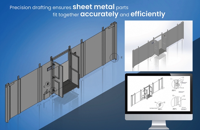
Precision drafting plays a pivotal role in ensuring that sheet metal parts fit together seamlessly, reducing errors, improving efficiency, and cutting down costs. In modern CAD drafting, precision is achieved using advanced tools, automated features, and simulation capabilities, which help engineers and designers create highly accurate models before manufacturing begins.
Enhancing accuracy and reducing errors

Precision drafting reduces manufacturing errors through automated tolerance control and dimensional accuracy verification. Modern CAD for sheet metal design enables comprehensive error detection and prevention throughout the sheet metal drawing process.
-
Importance of tight tolerances in sheet metal fabrication
Precise tolerance definition in sheet metal assemblies is critical for proper fitment and overall functional performance. It dictates the acceptable dimensional variation, directly impacting assembly processes and final product quality. Unlike traditional manual drafting, modern CAD-based precision drafting leverages Geometric Dimensioning and Tolerancing (GD&T) standards according to ASME Y14.5.
This standardized approach offers several key advantages:
- Consistent part accuracy across manufacturing batches: GD&T ensures consistent interpretation of design intent, reducing ambiguity and promoting uniformity across production runs.
- Compensation for material expansion and contraction: Especially crucial in high-temperature applications or with materials susceptible to dimensional changes, GD&T allows for controlled variation while maintaining functional integrity. This includes accounting for factors like thermal expansion coefficients.
- Standardized hole positioning and bend allowances: Precisely defined hole patterns and bend allowances ensure correct alignment and mating of parts during assembly, minimizing potential fit-up issues and facilitating automated assembly processes.
Tolerance analysis features within leading CAD platforms like SolidWorks, AutoCAD, and Inventor, often incorporating Monte Carlo simulations, empower designers to predict and address potential misalignments and tolerance stack-up issues early in the design process, preventing costly rework later.
-
Eliminating misalignment, incorrect fits, and rework costs
Precision drafting in CAD ensures proper component alignment and minimizes downstream manufacturing problems through several key mechanisms:
- Parametric constraints: These establish relationships between features and dimensions. Modifying one parameter automatically updates related dimensions, maintaining design intent and preventing inconsistencies across the model. This associativity is crucial for efficient design changes and revisions.
- 3D modeling: This enables designers to virtually assemble components and analyze interferences, clearances, and misalignments before physical prototypes are created. This digital verification significantly reduces the risk of discovering fit-up problems during production.
- Standardized hole and cutout placements: Precisely defined and standardized hole and cutout placements, often controlled through pattern features and GD&T callouts, guarantee matching features between components. This is essential for accurate fastener placement, welding operations, and other joining processes.
Leveraging the power of CAD and GD&T minimizes or eliminates misalignments and incorrect fits, substantially reducing rework costs, and scrap material, and maximizing first-pass manufacturing success.
Improving manufacturing efficiency
Precision drafting transforms manufacturing workflows by automating critical processes and optimizing production sequences. CAD integration streamlines operations from design to final assembly, substantially reducing production time and operational costs.
-
Reduction of waste and material costs
Use precision drafting in CAD software to improve material efficiency. Automated nesting algorithms optimize sheet metal layouts for cutting, minimizing scrap. They arrange parts to maximize material utilization and reduce offcuts, saving on raw material costs. Precision drafting prevents errors leading to material waste, such as overlapping cuts from improper scaling and incorrect hole placements requiring extra machining.
-
Streamlining CNC machining, laser cutting, and bending processes
Finalize your design in CAD and integrate it directly with CAM software. Generate G-code for CNC laser cutters, punch presses, and press brakes. Define bend allowances and K-factors for accurate bending. Provide precise cutting paths and machine-readable instructions, eliminating manual errors.
For instance, export a DXF file from AutoCAD to guide a laser cutter, ensuring accurate part dimensions.
-
Faster prototyping and design validation
Utilize virtual prototyping capabilities within your CAD software. Simulate stress tests, bending operations, and assembly fits before physical production. Test 3D models in motion to identify clearance issues in moving parts. Accelerate design iterations with digital modifications, reducing the need for multiple physical prototypes.
Leverage precision drafting in CAD to shorten lead times and ensure flawless sheet metal assembly.
Key benefits of precision drafting in sheet metal assembly and fitting

Precision drafting in CAD software significantly enhances fitment, material efficiency, and production speed in sheet metal fabrication. Modern parametric modeling, tolerance control, and automated nesting techniques ensure that every component is manufactured to exact specifications, reducing costly errors and delays.
Better fit and assembly of components
In sheet metal fabrication, even slight deviations in hole placement, bend allowance, or tolerance create misalignment. This leads to assembly failures, costly rework, and material waste. Precision drafting mitigates these issues by:
- Defining accurate sheet metal tolerances with GD&T (Geometric Dimensioning & Tolerancing). This standardized language ensures consistent interpretation of design intent and achieves proper alignment between mating parts.
- Employing parametric modeling to maintain consistent hole patterns, tab and slot designs, and fastener placements across multiple parts. This associativity allows for rapid design revisions and ensures consistent component interfaces.
- Conducting virtual fitment tests using CAD assembly simulations prior to physical prototyping. This digital verification process identifies potential clashes and interference issues early, reducing manufacturing lead times and costs.
Modern CAD software, including SolidWorks, Autodesk Inventor, and Creo Parametric, provides integrated tools for validating design integrity. Features like interference detection, dynamic clearance analysis, and part mating simulation allow engineers to detect misalignments and optimize assemblies for manufacturability and function before production begins. This approach minimizes downstream errors and contributes to a more efficient and robust manufacturing process.
Case Study: CAD drafting for sheet metal building products reduced TAT by 56%

A USA-based fabricator specializing in sheet metal building products and electrical enclosures sought to enhance their design capabilities. The client required detailed 3D CAD models and manufacturing drawings developed in accordance with Design for Manufacturing and Assembly (DFMA) guidelines to reduce turnaround times and accommodate fluctuating market demands.
Hitech CADD Services' team of skilled CAD engineers developed detailed 3D models and 2D manufacturing drawings using SolidWorks and AutoCAD. They also created a comprehensive CAD library to facilitate the reuse of standard components, thereby accelerating the design process. A thorough quality control process was implemented to ensure accuracy and adherence to DFMA principles.
The final deliverables led to:
- 56% reduction in turnaround time
- Improved design accuracy
- Enhanced resource allocation
Cost savings and reduced material waste
Precision drafting delivers financial benefits through optimized material utilization and waste reduction strategies. Advanced CAD systems enable manufacturers to maximize resource efficiency while maintaining product quality and dimensional accuracy.
-
Precision cutting and nesting strategies to optimize material usage
Material cost is a primary driver in sheet metal fabrication. Employing CAD-based nesting strategies minimizes waste by:
- Optimizing part layouts to maximize sheet usage, potentially achieving up to 90% material utilization.
- Strategically arranging parts to reduce offcuts and scrap, including considerations for grain direction and material properties.
- Utilizing common-line cutting, where parts share cut lines, minimizing both cutting time and kerf loss.
Industry-standard CAD software, including AutoCAD, Inventor, and SolidWorks, provide automated nesting features. These generate optimized layouts within seconds, impacting time and helping in cost reduction and material savings.
-
Lowering scrap rates and improving sustainability
Precision CAD drafting eliminates manual drafting errors, preventing:
- Overcuts and incorrect dimensions that lead to scrapped parts, a significant source of waste in traditional workflows.
- Costly rework due to misalignment or dimensional inaccuracies, further reducing material efficiency.
- Unnecessary raw material consumption, contributing to a more sustainable fabrication process and aligning with lean manufacturing principles.
Efficient CAD drafting maximizes sheet metal usage. This directly translates to lower material costs, reduced environmental impact, and improved overall operational efficiency.
Faster production and reduced lead times
Precision drafting accelerates production cycles by streamlining design-to-manufacturing workflows and minimizing process bottlenecks. CAD integration enables rapid design validation, automated programming, and efficient production planning, significantly reducing overall lead times.
-
How well-drafted designs enable quick approvals and manufacturing
A well-structured CAD model streamlines your production process, directly impacting your bottom line.
- Standardized drafting templates, adhering to industry standards like ASME Y14.100, promote consistency and expedite approvals. This reduces ambiguity and ensures clear communication across your team.
- Automated dimensioning and BOM generation, leveraging tools like Feature Manager Design Tree, free up your engineering resources for more complex tasks. Accurate BOMs minimize procurement errors and delays.
- Direct integration with CNC and laser-cutting machines, using industry-standard protocols like G-code, ensures a seamless transition from digital design to physical product. This reduces manual intervention and the risk of human error.
Consider a DXF file exported from SolidWorks or AutoCAD. This file imports directly into a CNC laser cutter, eliminating manual programming and accelerating your prototyping and production phases.
-
Minimizing time spent on revisions and modifications
Parametric modeling allows for design changes to propagate instantly across multiple parts, eliminating the need for time-consuming redrawing. Design intent capture ensures modifications maintain design integrity.
Version control within your CAD software, using platforms like PDM (Product Data Management), guarantees you are working with the latest approved design, preventing costly errors and rework. A clear audit trail enhances traceability.
Rapid prototype testing with 3D CAD models, utilizing technologies like 3D printing, reduces your reliance on multiple physical iterations. This allows for faster design validation and accelerates product development cycles.
Precision CAD drafting empowers you to shorten lead times, enhance production efficiency, and achieve first-pass accuracy. This translates to faster product delivery, reduced development costs, and increased customer satisfaction.
Wrapping up
Precision drafting has transformed sheet metal manufacturing through advanced technical specifications and process control. Integrating CAD systems, automated manufacturing, and comprehensive tolerance analysis delivers measurable improvements in production outcomes.
Manufacturing organizations implementing precision drafting systems achieve reductions in assembly time, material waste, and quality control costs. These improvements stem from accurate component specifications and validated assembly processes. As drafting technology advances, metal fabrication companies will gain additional capabilities in simulation and optimization, driving continued improvements in sheet metal assembly and sheet metal fitting operations.


